This development board is fully compatible with the Raspberry Pi Pico series and features a wide range of resource modules and expansion I/O ports. It includes a DS1302 real-time clock module, a full-color RGB LED module, a microphone module, an audio module, a speaker module, an SD card module, two function buttons, and six Grove I/O connectors. Additionally, it supports lithium battery charging, allowing both Pico-to-PC communication and battery charging via a single data cable.
Product Features
- Rich resource modules and expanded I/O ports
- Example programs provided for development board modules
- Transparent working status: each GPIO port has an indicator LED that lights up when in use
- Built-in lithium battery charging function; a single Type-C cable enables both communication with a computer and battery charging
Product Specifications
Power Supply Voltage | 5V (provided by Pico) |
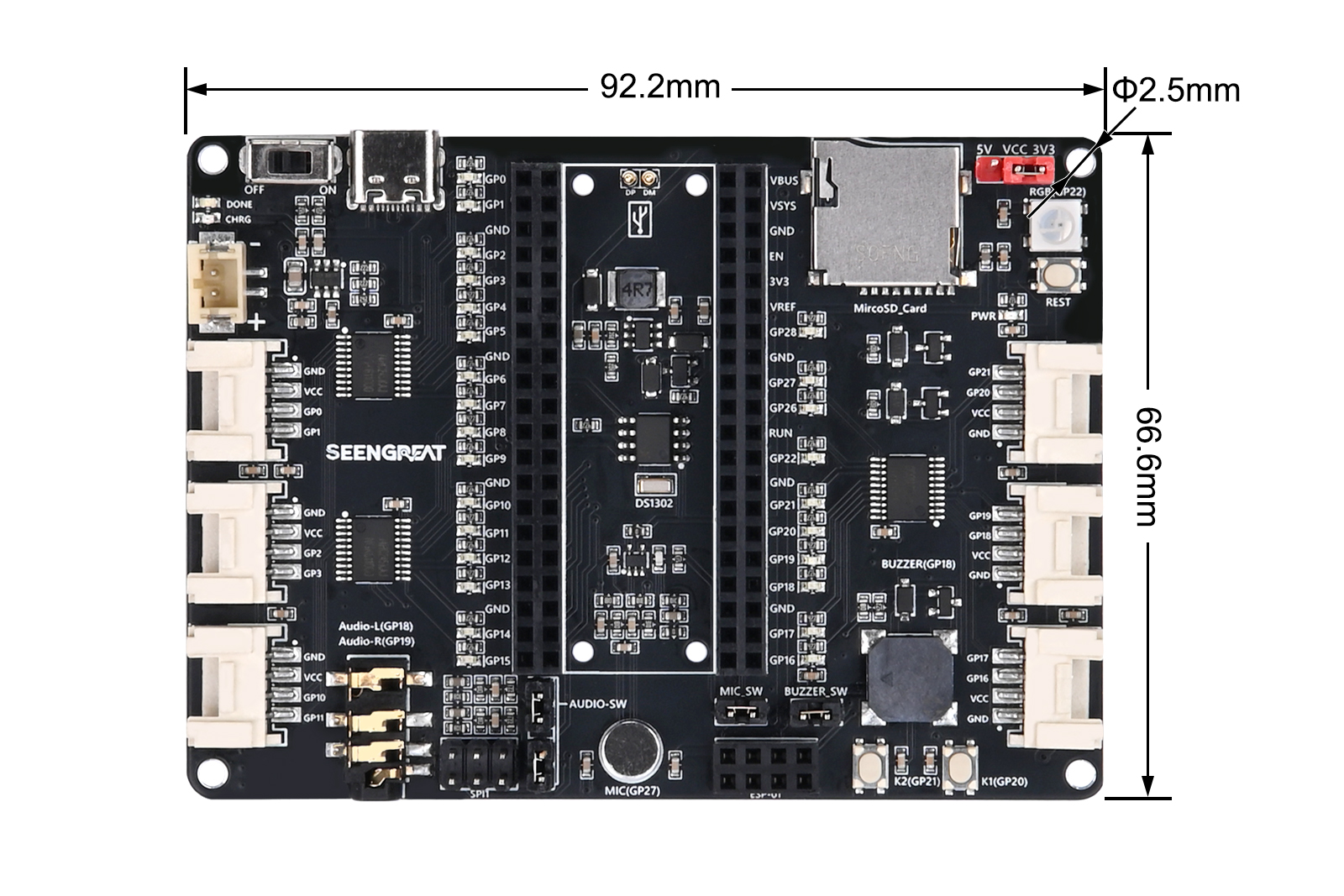
Dimensions | 92.2mm(L)×66.6mm(W) |
Functional Features
Form Factor
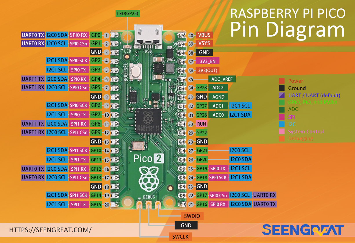
Raspberry Pi Pico Pinout
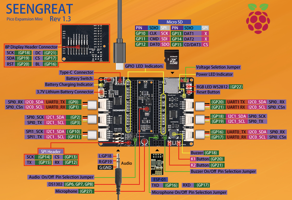
Pico Expansion Mini pinout
Usage
1.1 Hardware Description
1.1.1 Overview of Hardware Pin Usage
Resource Module | I/O Pins Used |
DS1302 Clock | GP6、GP7、GP8 |
RGB Seven-Color LED | GP22 |
Microphone Module | GP27 |
Audio Module | GP18、GP19 |
Buzzer | GP18 |
SD Card Slot | GP10、GP11、GP12、GP13、GP14、GP15 |
Grove I/O Connectors | GP0、GP1 |
GP2、GP3 | |
GP10、GP11 | |
GP16、GP17 | |
GP18、GP19 | |
GP20、GP21 | |
ESP-01 Female Header | GP16、GP17 |
SPI1 Header | GP12、GP13、GP14、GP15 |
8P Display Header | GP16、GP17、GP18、GP19、GP20、GP21 |
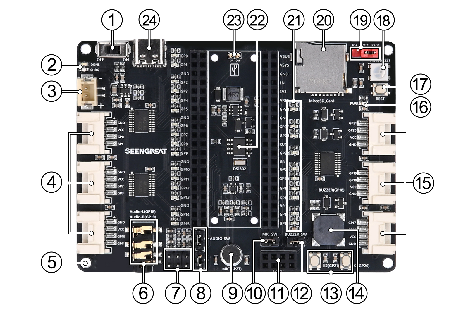
1.1.2 Function Introduction
- A 2x20PIN female header, compatible with the Raspberry Pi Pico series, allows for easy connection to the Raspberry Pi Pico expansion board or external devices using DuPont wires. Clear pin function labels and working status LEDs are provided on both sides of the header for easy usage and measurement.
- There are 6 HY-2.0-4P connectors for connecting 2.0mm pitch ribbon cables, providing a convenient way to connect additional functional modules. A pin header in the upper left corner allows you to select the power voltage for these connectors. When the jumper cap is placed on the 5V side, the connected modules are powered by 5V; when switched to the 3.3V side, they are powered by 3.3V. Note: All VCC pins on the external HY-2.0-4P connectors are connected together, so once a voltage is selected, the voltage for all connected modules will be the same.
- The Raspberry Pi Pico does not have a reset button, but this product includes a reset button, making it easier for users to debug or upload programs.
- The board includes an onboard microSD card slot, full-color RGB LED (WS2812), standard 3.5mm audio jack, buzzer, microphone, DS1302 clock, function buttons, battery management module, and more.
1.2 Download and install Thonny
① Download Thonny installation package: https://thonny.org
② After installing Thonny, you can use a Type-C cable to connect to the onboard USB connector for communication with the Raspberry Pi Pico. There is no need for an additional Micro USB data cable.
Insert the Raspberry Pi Pico into the board in the correct orientation. While the board is powered off, press and hold the BOOTSEL button on the Pico, then connect the Type-C cable to both the computer and the board. Your computer will detect a new drive labeled RPI-RP2. Drag and drop the adafruit-circuitpython-raspberry_pi_pico-en_US-7.3.3.uf2 file into the RPI-RP2 drive to complete the setup.
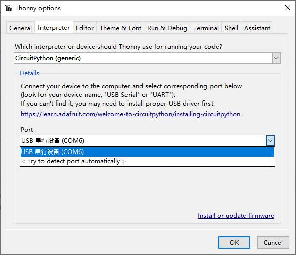
③ Open Thonny, then from the top menu, select Run → Configure interpreter. In the Configure interpreter window, choose CircuitPython (generic), and select the connected serial port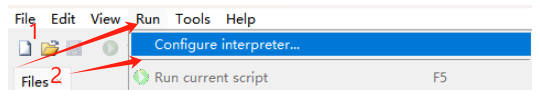
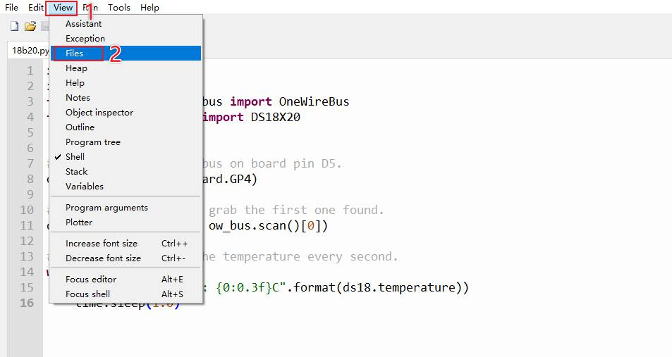
④ Open the Shell and Files windows from the View menu to monitor program output and debug your code
2.1 Demo Code Usage
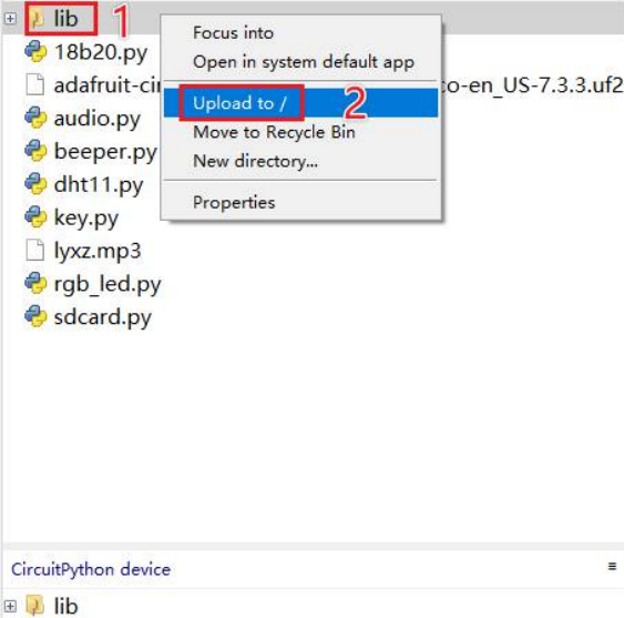
Open the example code directory, and upload the "lib" folder to the Raspberry Pi Pico
① Full-Color RGB LED Demo Program:
Right-click the rgb_led.py file in the example code directory and upload it to the Pico. Then, click the "Run current script" button or press F5 to execute the script. You will observe that the full-color LED continuously changes colors
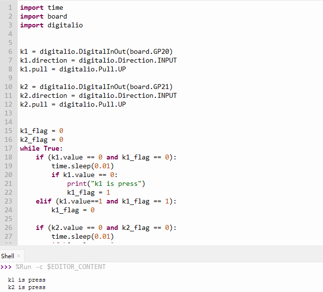
② Function Button Demo Program:
Right-click the key.py file in the example code directory and upload it to the Pico. Then, click the "Run current script" button or press F5 to execute the script. When you press the K1 or K2 button, you can observe the corresponding button press information in the Shell window.
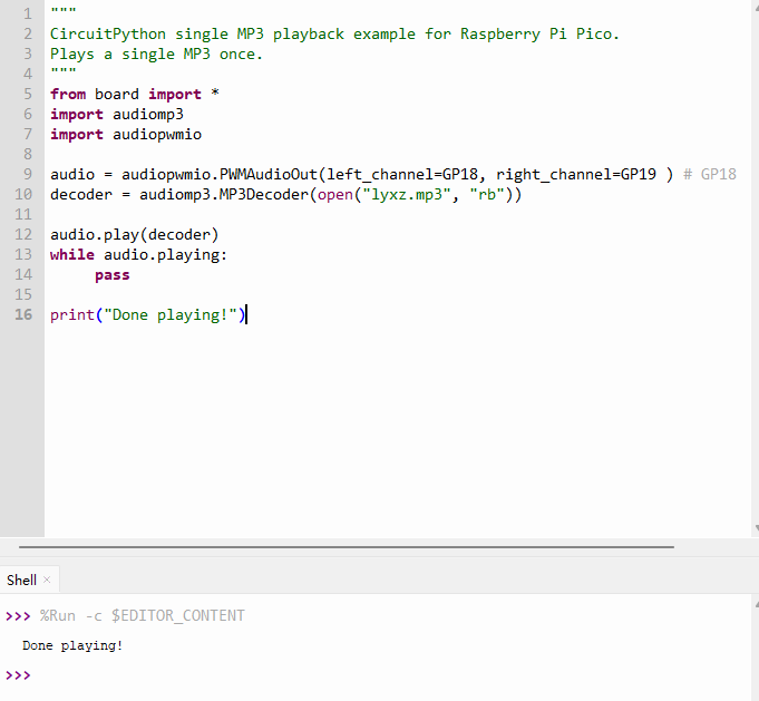
③ Audio Demo Program:
Insert a 3.5mm wired headphone into the onboard audio connector, and use a jumper cap to connect the two 2-pin headers for Audio-SW. Upload the Audio.py file and lyxz.mp3 to the Pico, then click the "Run current script" button or press F5 to run the script. The headphone will play the lyxz.mp3 music, and after playback is finished, the Shell window will print "Done Playing!

④ Buzzer Demo Program:
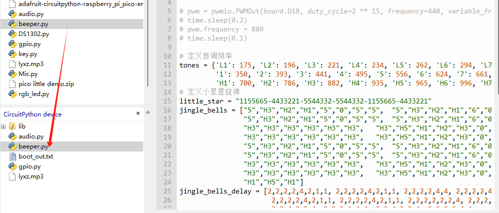
Right-click the beeper.py file in the example code directory and upload it to the Pico. Then, connect the BUZZER_SW header using a jumper cap. Click the "Run current script" button or press F5 to execute the script, and the buzzer will play a musical melody.
⑤ DS1302 Clock Function Demo Program:
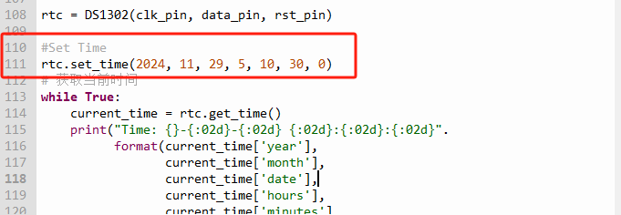
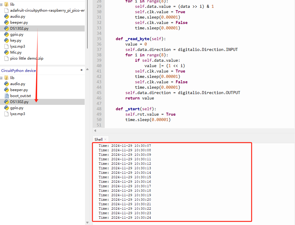
Right-click the DS1302.py file in the example code directory and upload it to the Pico. You can set the time on line 111 of the code. Then, click the "Run current script" button or press F5 to execute the script; the Shell window will display the clock's progress. Once you've set the time, comment out the time-setting code on line 111 and run the program again—the clock will continue to increment based on the previously set time.
⑥ Microphone Demo Program:
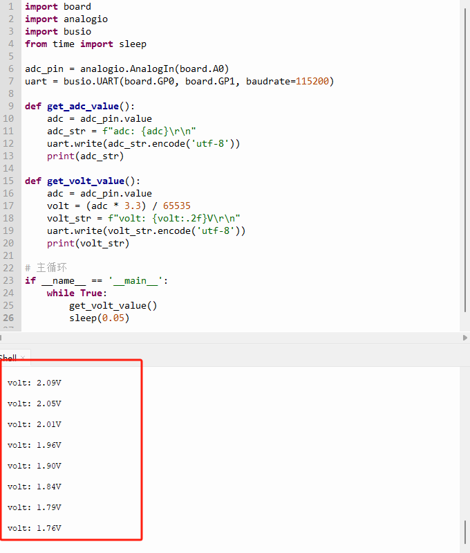
Right-click the Mic.py file in the example code directory and upload it to the Pico. Then, connect the Mic_SW header using a jumper cap. Click the "Run current script" button or press F5 to execute the script. At this point, simply producing some sound will allow you to observe the voltage changes on the Pico's ADC pin.
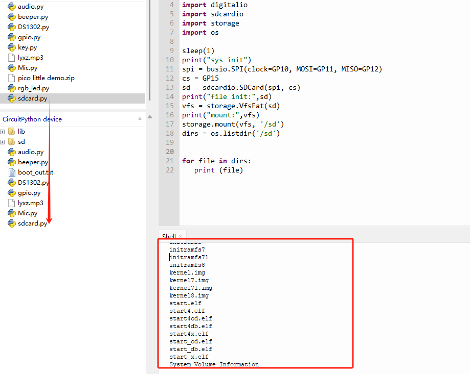
⑦ SD Card Slot Detection Function Demo Program:
Right-click the sd_card.py file in the example code directory and upload it to the Pico. Then, ensure that your SD card is formatted with a FAT32 or FAT file system. Click the "Run current script" button or press F5 to execute the script, and you will see the Shell window display the names of the files and folders on the SD card.