Ⅰ
Directions
1.1 Product Overview
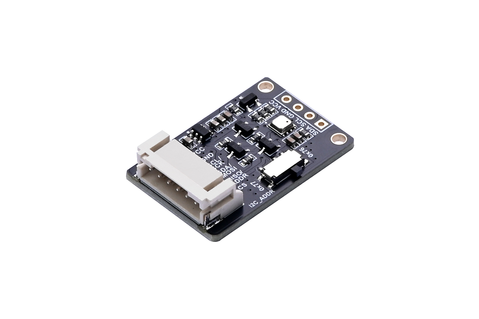
This product is a high-precision environmental sensor featuring the BME68X sensor, which enables monitoring of temperature, humidity, atmospheric pressure, and VOC gases. The chip's temperature measurement range is -40 to +85°C, humidity range is 0–100%, and atmospheric pressure range is 300–1100 hPa.
The module connects to the development board via a PH2.0 6-pin cable for environmental monitoring. The board supports SPI/I2C interfaces, and we provide example programs for Arduino, Raspberry Pi, Raspberry Pi Pico, and ESP32 platforms. These example programs allow real-time monitoring of temperature, humidity, atmospheric pressure, and gases.
1.2 Product Specifications
Sensor Chip | BME680 | BME688 |
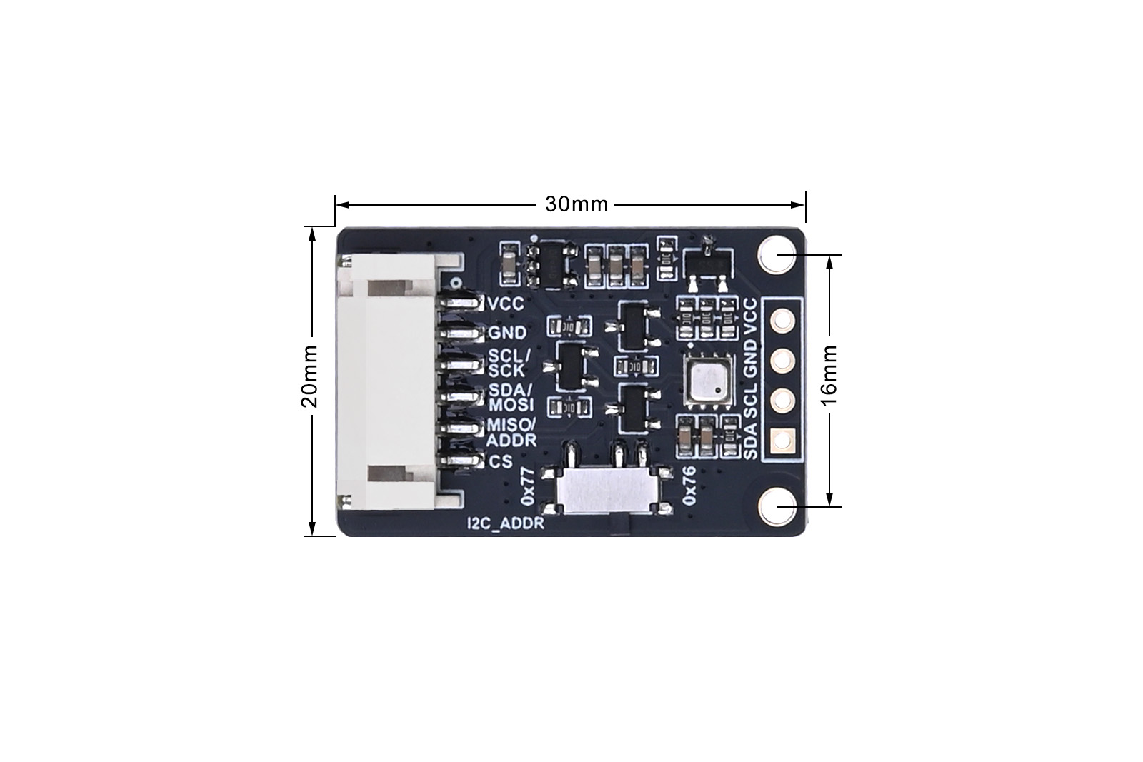
Dimensions | 30mm (L) × 20mm (W) | |
Signal Interface | I2C/SPI | |
Supply Voltage | 3.3V/5V | |
Temperature Range | -40 to +85℃ | |
Temperature Accuracy | ±1℃ (0–65℃) | ±0.5℃ (0–65℃) |
Humidity Measurement | 0–100%RH (Resolution: 0.008%RH, Accuracy: ±3%RH) | |
Pressure Range | 300–1100 hPa | |
Pressure Accuracy | ±0.6hPa (0–65℃) | |
Gas Detection | VOC gas variation detection (Bosch software required for IAQ calculation) | VOC and VSC gas variation detection (Bosch software required for IAQ calculation and integrated AI functions) |
1.3 Dimensions
Ⅱ Usage
The onboard I2C address setting slide switch is by default in the 0x77 position. When using SPI communication, ensure the switch is also set to 0x77.
Note: In the example programs for all platforms, the gas detection result is represented as a resistance value. To convert this to the IAQ (Indoor Air Quality) index, you must use the official BSEC software library (non-open-source). Bosch imposes certain restrictions and licensing on the use of this software library. Users should review the documentation and terms before integrating it. The link to the BSEC software library is: https://www.bosch-sensortec.com/software-tools/software/previous-bsec-software-versions/
2.1 Resources Overview
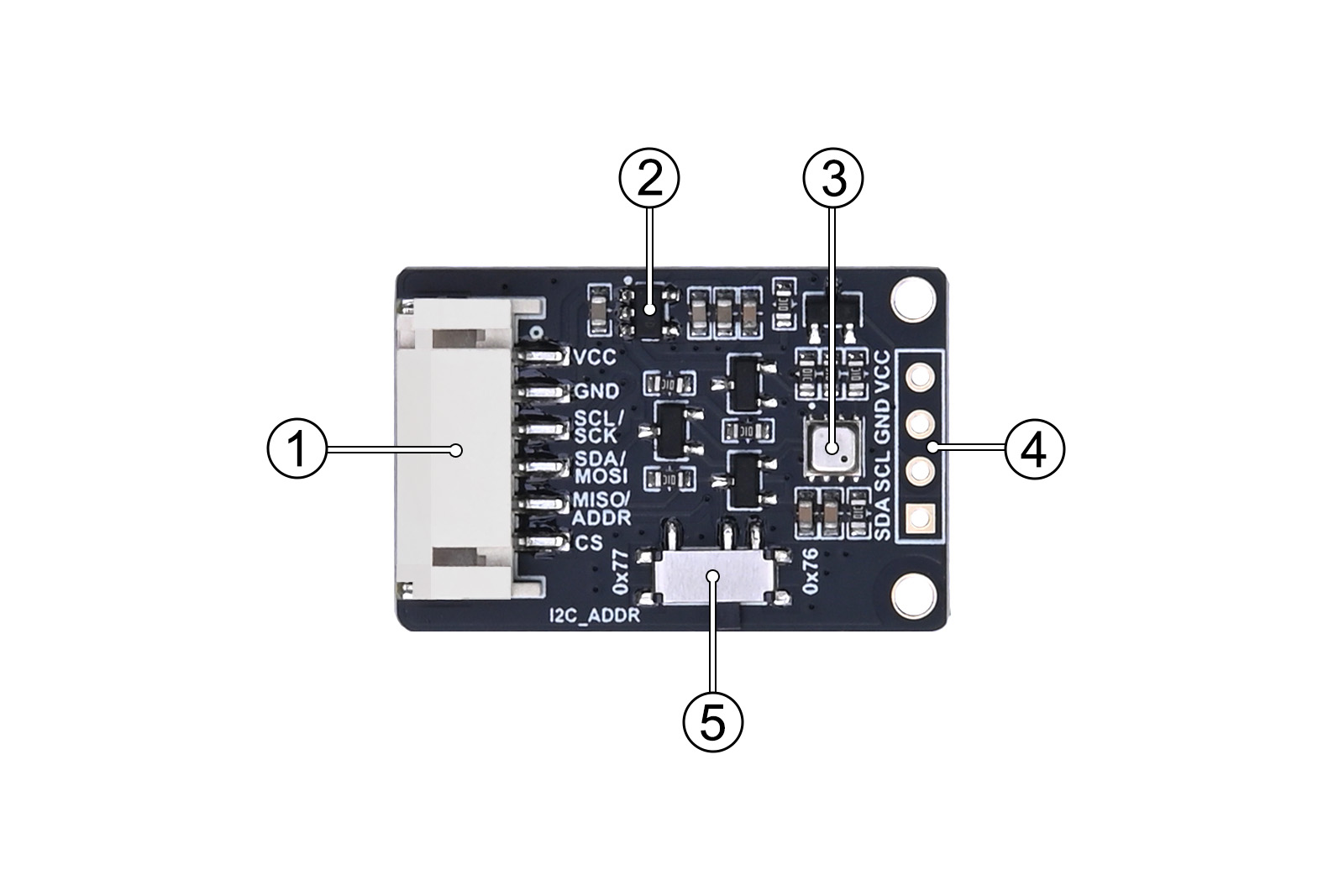
- PH2.0 6-PIN Connector: Used for connecting the sensor module to the development board.
- RT9193-33 Linear Regulator: Provides a stable power supply with low power consumption and quick startup time.
- BME68X Sensor: The core component for measuring temperature, humidity, pressure, and gas levels.
- I2C Interface Pads: Solder pads for I2C communication interface.
- Slide Switch for I2C Address Configuration: Used to set the I2C address for communication.
2.2 Interface Definition
Pin Function | I2C | SPI |
VCC | Power positive (3.3V/5V) | Power positive (3.3V/5V) |
GND | Power ground | Power ground |
SCL/SCK | Clock line | Serial clock |
SDA/MOSI | Data line | Master Output/Slave Input |
MISO/ADDR | Not connected (NC) | Master Input/Slave Output |
CS | Not connected (NC) | Chip select signal |
Table 2-1: BME68X Environmental Sensor Pin Definition
2.3 Raspberry Pi Example Usage
The example codes for the Raspberry Pi platform is available in two versions: one using the lgpio library and the other using the wiringpi library. The lgpio library is used for the bookworm system, while the wiringpi library is used for the bullseye system.2.3.1 Raspberry Pi Interface Definition
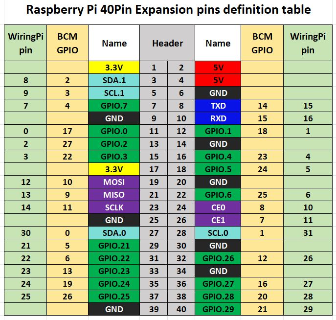
The example codes for the Raspberry Pi use different pin numbering systems: the lgpio library uses the BCM pin numbering, while the wiringpi library uses the wiringpi pin numbering. The wiring connections to the Raspberry Pi board are defined as follows in Table 2-2:
BME68X | BCM Pin Number (I2C) | wiringPi Pin Number (I2C) | BCM Pin Number (SPI) | wiringPi Pin Number (SPI) |
VCC | 3.3V | 3.3V | 3.3V | 3.3V |
GND | GND | GND | GND | GND |
SCL/SCK | SCL1 (D3) | SCL1 (P9) | SCLK (D11) | SCLK (P14) |
SDA/MOSI | SDA1 (D2) | SDA1 (P8) | MOSI (D10) | MOSI (P12) |
MISO/ADDR | NC | NC | MISO (D9) | MISO (P13) |
CS | NC | NC | D25 (P6) | P6 |
Table 2-2: Pin Definition for Module to Raspberry Pi Wiring
2.3.2 Wiringpi Library Installation
sudo apt-get install wiringpi
wget https://project-downloads.drogon.net/wiringpi-latest.deb
Raspberry Pi 4B version upgrade
sudo dpkg -i wiringpi-latest.deb
gpio -v #
If version 2.52 appears, it means that the installation has been successful
#For the Bullseye branch system, use the following command:
git clone https://github.com/WiringPi/WiringPi
cd WiringPi
. /build
gpio -v #
# If you run gpio -v, version 2.70 will appear. If it does not appear, it means the installation went wrong.
#For Python 2.x
pip install wiringpi#For Python 3.x
pip3 install wiringpiNote: If the installation fails, you can try the following compilation and installation:
git clone --recursive https://github.com/WiringPi/WiringPi-Python.gitNote: The --recursive option can automatically pull submodules, otherwise you need to download them manually.
Enter the WiringPi-Python folder you just downloaded, enter the following commands to compile and install:
# For Python 2.x
sudo python setup.py installsudo python3 setup.py installIf the following error occurs:

Now enter the command 'sudo apt install swig' to install swig. After completion, execute 'sudo python3 setup.py install' to compile and install.
If a message similar to the following appears, it means the installation is successful.

2.3.3 lgpio library installation
For the bookworm system, the example codes uses the lgpio library. The following is the installation command for the library:
wget https://github.com/joan2937/lg/archive/master.zip
unzip master.zip
cd lg-master
make
sudo make install
2.3.4 Enable I2C and SPI interfaces
sudo raspi-configEnable the I2C interface:
Interfacing Options -> I2C -> Yes
Enable the SPI interface:
Interfacing Options -> SPI -> Yes
Restart your device
sudo reboot2.3.5 I2C address detection
When using I2C communication method for wiring, you can first detect the address of the sensor and install the i2c-tools tool:
sudo apt-get install i2c-toolsUse the terminal command to view the connected I2C devices:
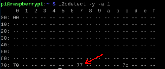
i2cdetect -y -a 1If 0x76 or 0x77 appears in the result, it means that the Raspberry Pi successfully detects the address of BME68X. The I2C_ADDR slide switch is at 0x77 by default. At this time, 0x77 will appear in the result, as shown in Figure 2-2 below:
2.3.6 Run the example codes
C example codes:
Take the I2C communication method of the lgpio library as an example, enter the /demo codes/raspberry_pi/lgpio/c file path, and then execute the following command:
sudo make clean
sudo make
sudo ./main
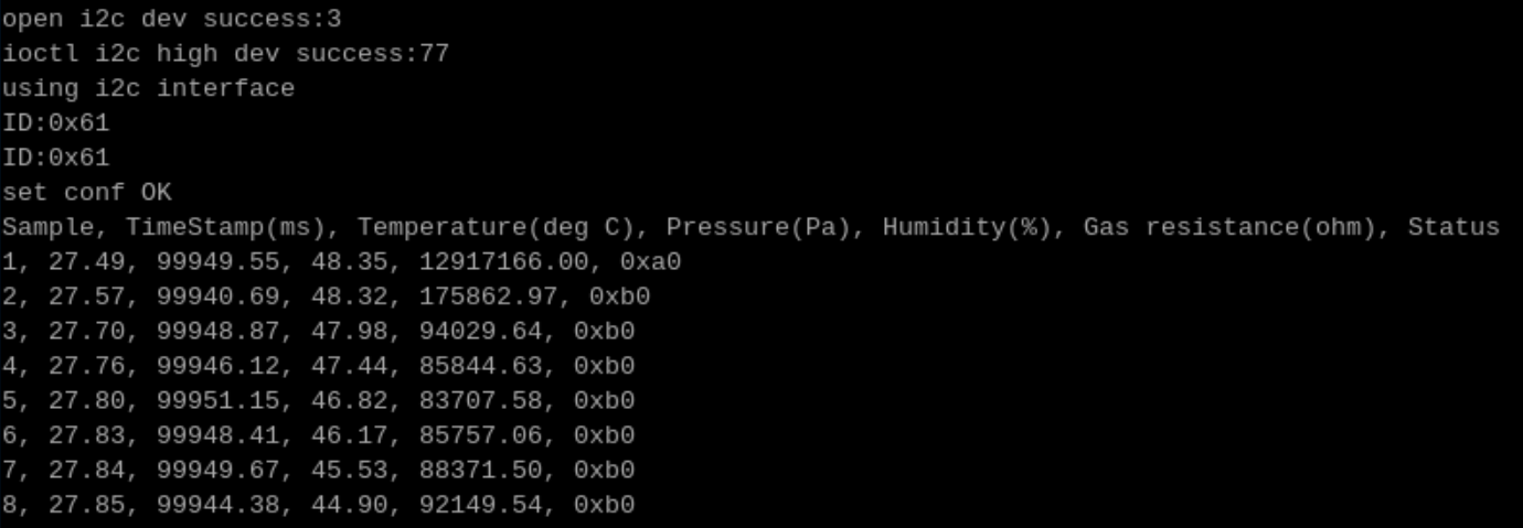
You can see the real-time detected temperature, humidity, atmospheric pressure and gas resistance information on the Raspberry Pi terminal, as shown in Figure 2-3 below:
Python example codes:
Enter the /demo codes/raspberry_pi/lgpio/python file path and execute the following command:
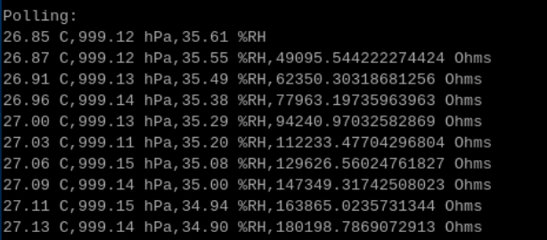
sudo python3 read-all.pyThe running result is shown in Figure 2-4:
SPI Communication Mode:If the user prefers to use SPI communication, the BME68X module should be wired according to the SPI pinout defined in Table 2-2. Additionally, set the "I2C_ADDR" slide switch to the 0x77 position. In the Python example codes, modify the "COMMUNICATION_MODE = 1" statement in the constants.py file to "COMMUNICATION_MODE = 0", and then rerun the program. For the C language example, modify the "#define USE_IIC 1" line in the bme68x_defs.h file to "#define USE_IIC 0", then recompile and run the program.
2.4 Arduino Example Usage
2.4.1 Wiring Instructions
The wiring between the BME68X sensor and the Arduino Uno development board is shown in Table 2-3:BME68X | I2C | SPI |
VCC | 3.3V/5V | 3.3V/5V |
GND | GND | GND |
SCL/SCK | SCL | D13 |
SDA/MOSI | SDA | D11 |
MISO/ADDR | NC | D12 |
CS | NC | D10 |
Table 2-3: Pin Definition for Module to Arduino Uno Wiring
The wiring between the BME68X sensor and the Arduino Mega development board is shown in Table 2-4:
BME68X | I2C | SPI |
VCC | 3.3V/5V | 3.3V/5V |
GND | GND | GND |
SCL/SCK | SCL1 | D52 |
SDA/MOSI | SDA1 | D51 |
MISO/ADDR | NC | D50 |
CS | NC | D53 |
Table 2-4: Pin Definition for Module to Arduino Mega Wiring
2.4.2 Library Installation
1. Navigate to the directory demo codes\Arduino\bme68X, and open the bme68X.ino file using the Arduino IDE.
2. Go to Sketch > Include Library > Manage Libraries.
3. In the library search bar, type BME68x to find the BME68x Sensor Library by Bosch.
4. Click Install to add the library to your project.
2.4.3 Running the Program
The example program is set to I2C communication mode by default, with the I2C address set to 0x77. The I2C_ADDR slide switch is also set to the 0x77 position by default.Once verified, upload the program to the development board. Then, go to Tools > Serial Monitor, open the serial monitor, and set the baud rate to 115200. Observe the changes in sensor data as shown in Figure 2-5.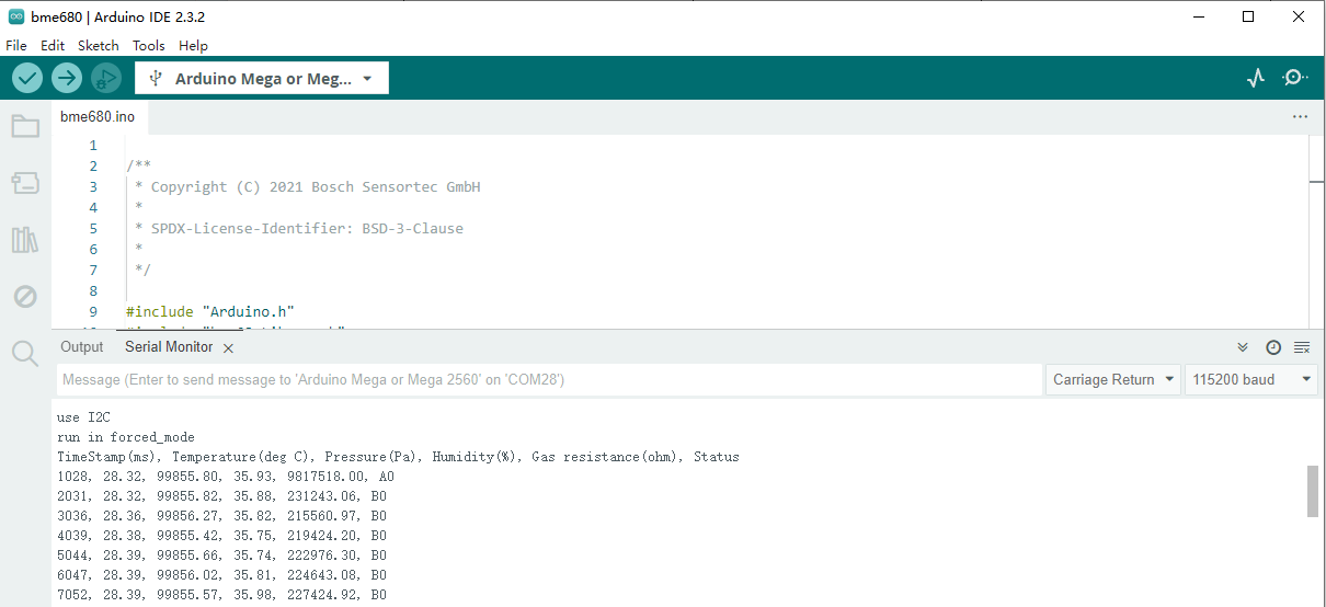
To use 0x76 as the sensor address, set the I2C_ADDR slide switch to the 0x76 position and modify the example program by changing:
#define ADDR_I2C 0x77 // I2C
to:
#define ADDR_I2C 0x76 // I2C
If you wish to use SPI communication, connect the BME68X module according to the SPI wiring diagrams in Table 2-3 or Table 2-4. Set the I2C_ADDR slide switch to the 0x77 position, and then modify the example program by changing:
#define USE_IIC 1
to:
#define USE_IIC 0
2.5 ESP32 Example Usage
The example program uses the ESP32-WROOM-32E module.2.5.1 Wiring Instructions
The wiring between the BME68X sensor and the ESP32 development board is shown in Table 2-5:BME68X | I2C | SPI |
VCC | 3.3V | 3.3V |
GND | GND | GND |
SCL/SCK | P22 | P18 |
SDA/MOSI | P21 | P23 |
MISO/ADDR | NC | P19 |
CS | NC | P27 |
Table 2-5: Pin Definition for Module to ESP32 Wiring
2.5.2Arduino IDE environment configuration
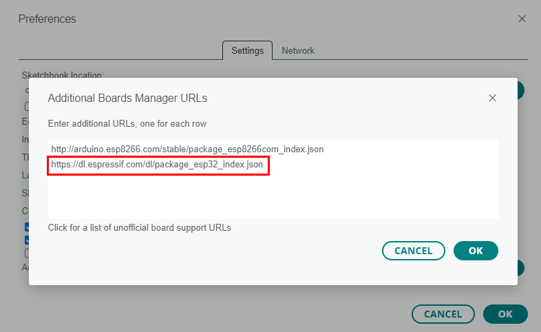
Open Arduino IDE, click the menu "File->Preferences->Settings", and then add the development board manager URL https://dl.espressif.com/dl/package_esp32_index.json in "Additional boards manager URLs:", as shown in Figure 2-6:
Download the packages compressed package, and copy the esp32 in the unzipped packages folder to the following path: C:\Users\Admin\AppData\Local\Arduino15\packages, where "Admin" needs to be replaced with your own user name.
2.5.3 Library installation and program running
For this step, please refer to the contents of chapters 2.4.2 and 2.4.3.
2.6 Raspberry Pi Pico demo usage
The example program supports Raspberry Pi Pico and Pico 2, both of which have the same wiring definition. This platform only provides example programs in Python language.
2.6.1 Wiring instructions
The wiring of BME68X and Pico/Pico 2 development board is shown in Table 2-6 below:
BME68X | I2C | SPI |
VCC | 3.3V | 3.3V |
GND | GND | GND |
SCL/SCK | GP7 | GP10 |
SDA/MOSI | GP6 | GP11 |
MISO/ADDR | NC | GP12 |
CS | NC | GP13 |
Table 2-6 Pin definitions for connecting the module to the Pico/Pico 2 development board
2.6.2 Use environment configuration
1. uf2 library
Press and hold the BOOTSEL button on Pico/Pico 2, and then connect Pico/Pico 2 to the computer via a USB cable. At this time, a new disk will be generated in my computer. Pico corresponds to "RPI-RP2" and Pico 2 corresponds to "RP2350". Then copy the corresponding uf2 file (under the demo codes/Pico/ path) to the disk. Pico uses RPI_PICO-20241025-v1.24.0.uf2, and Pico 2 uses RPI_PICO2-20240923-v1.24.0-preview.321.g0ff782975.uf2. The uf2 file may be updated. You can also download the updated version of uf2 firmware from the following website: https://micropython.org/download/.
2. Interpreter settings
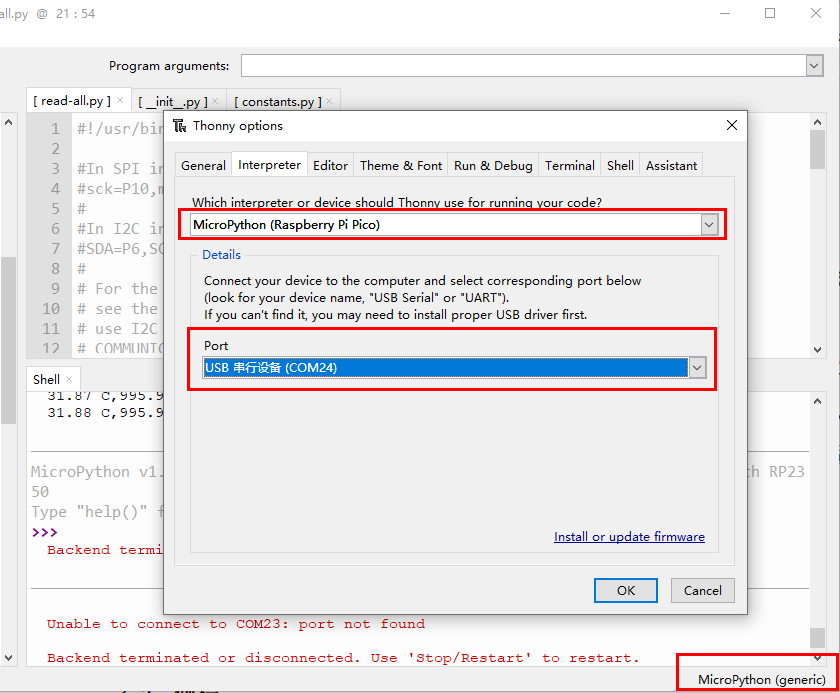
Open the Thonny software, then click Tools->Options...->Interpreter to select the interpreter port of the device, as shown in Figure 2-7 below. The Interpreter is selected as "MicroPython (Raspberry Pi Pico)", and the Port is selected as the corresponding USB port.
2.6.3. Run the example program
Click View->Files in Thonny, then select "This computer" in the window that pops up on the left side of the software. If it does not pop up, click the red Stop/Restart backend (Ctrl+F2) button, then select the bme68X folder of the example program in the window, right-click and select "Upload to /", upload bme68X to Pico, and also upload read-all.py to Pico, then double-click read-all.py, and finally click the "Run Current Script (F5)" button. At this time, the Shell window will output the corresponding information, as shown in Figures 2-8 and 2-9:
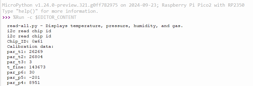
Figures 2-8
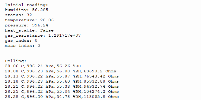
Figures 2-9
The example program uses I2C communication by default. If the user needs to use SPI driver instead, connect the BME68X module according to the SPI bus wiring method in Table 2-6, and set the "I2C_ADDR" slide switch to 0x77. Then change the "COMMUNICATION_MODE = 1" statement in the constants.py file in the python example program to "COMMUNICATION_MODE = 0".
Data Resources
3.3 data sheet
